Android Line Following Robot
June 10, 2016
Overview
This is the final project for the course: ME433 Advanced Mechatronics, Northwestern University
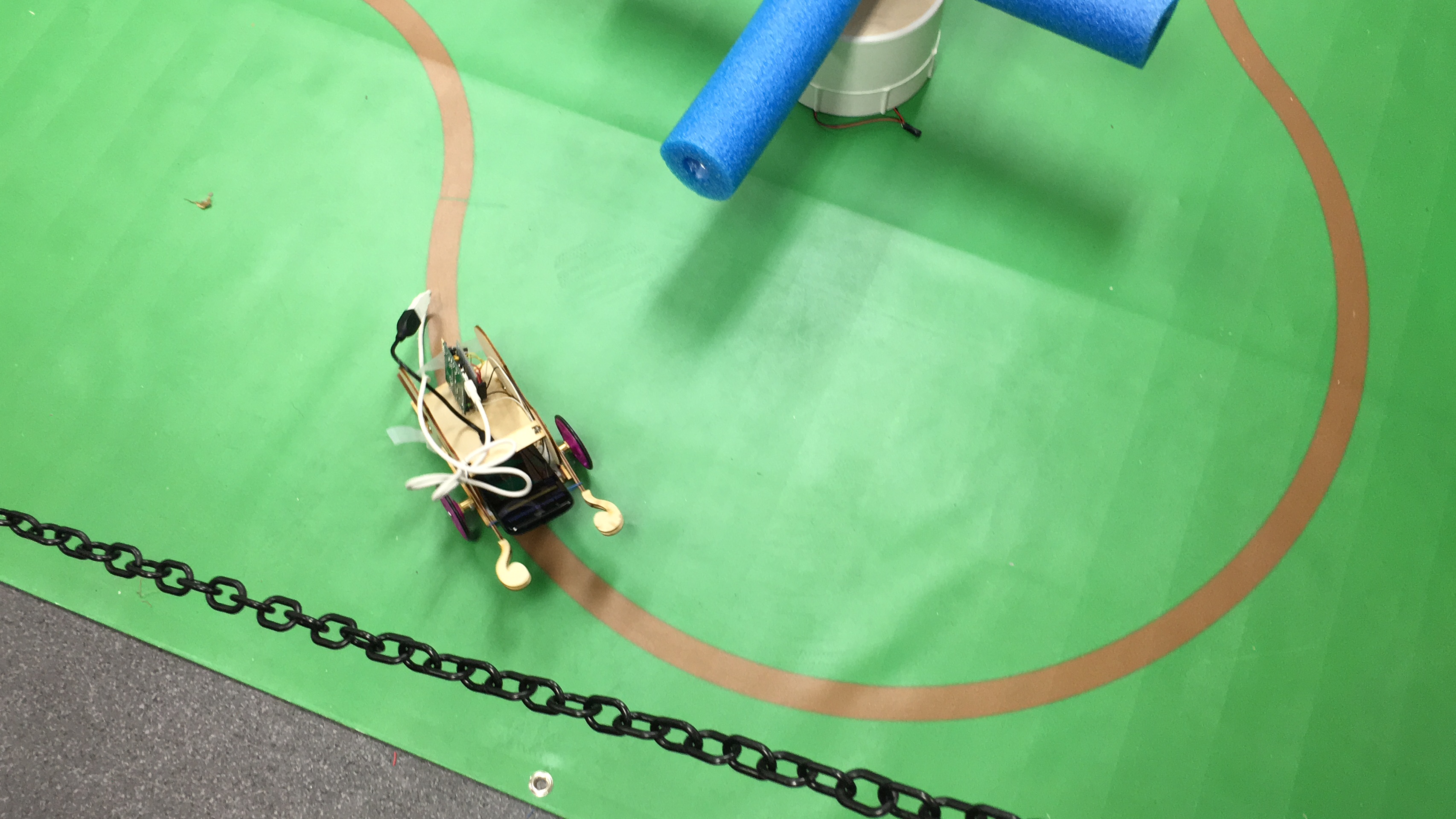
I designed and fabricated a mobile robot using 3D printer and laser cutter and soldered the PCB board after schematic design. I also created an camera app in Android Studio using JAVA and programmed a PIC32 microcontroller in C to receive the image processing results from the phone via USB CDC and perform PWM control on motors.
The android camera app used one slide bar to control the threshold. Since the map is colored in green and brown, the red pixel was considered for track detection. If (255 - red pixels) smaller than threshold value, that pixel was set to black. There were 6 points plotted on the camera app to show the center of mass (COM).
The PWM duty cycle ratio to control motors was adjusted as following: The default is 100% PWM output for both left and right motors. When the COM is larger than 320, I decrease the PWM of the right motor by (COM3-320)/320. When the COM3 is smaller than 320, I decrease the PWM of the right motor by (320-COM3)/320. Therefore, the robot was able to effectively tracking the path.